While many new theoretical discussions continue showing up here on TW, it’s been a long time that a new theremin design which works in practice and can easily be built has been published in these forums.
That’s why I decided now to publish the following circuit. It’s another simple pitch-only theremin design which I have developed over the last 3 years, first as a response to the numerous demands which I got from High school students for their projects. Later, the Dutch thereminist Wilco Botermans and me started using this circuit during DIY-workshops for beginners which we organized in many European countries. Finally it was also used by Wilco for an installation with 5 of these theremins, installed in Coke bottles, in a setup which allowed the public to move within the common field, producing polytonal sounds.
Wilco’s wife Jessica gave this circuit its name “Thierrymin”, because it is very small and because she wanted to honor its inventor…
Principle of Operation:
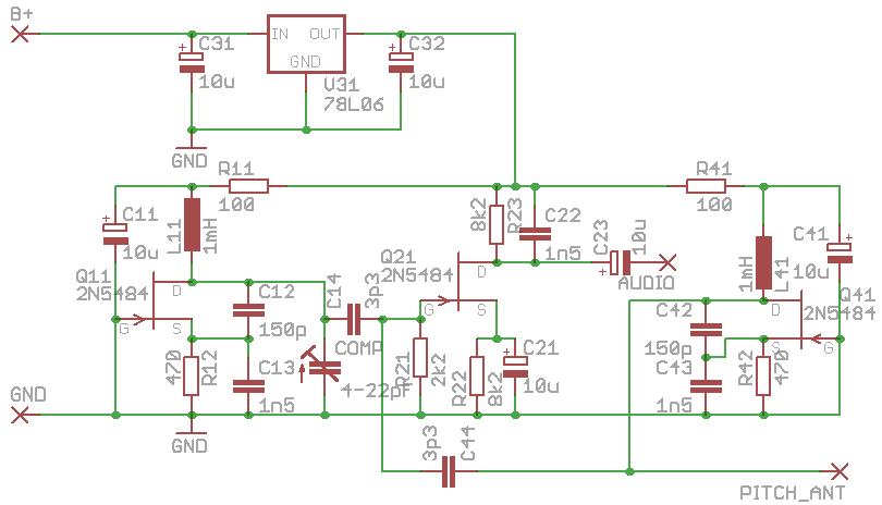
There are two identical oscillators around J11 and J41 working around 410kHz. One will be connected to the pitch antenna (see below), the other has a small variable capacitor which allows to adjust its frequency and thus do the coarse pitch tuning. While the 2N5484 FET transistors are now out of production, they can still be found almost everywhere, but any other N-JFET with a pinch-off voltage of 1.5V will do. The oscillators work in a grounded gate configuration which provides best independence of the internal junction capacitances. That makes them fairly stable in this simple circuit. The inductances L11 and L41 are simple 1mH fixed inductors which are not critical, as long as their self resonant frequency is above 800kHz. R11/C11 and R41/C41 decouple both oscillators which gives the circuit a nice low audio frequency response, together with the small coupling capacitors C14 and C44.
The mixer around Q21 is works as an active rectifier due to the high source bias resistor R22, so that only the positive halves of the sum signal at the gate will pass through. The advantage compared to a simple diode mixer is a better decoupling between output and input, so that the output load (the connected audio cable and amplifier) will not affect the mixer’s response. C22 filters the remaining RF component from the audio output signal.
V31 is a simple 6V voltage regulator which allows the circuit to be operated from either a 9V block battery or any DC power supply between 9 and 12V. As a pitch antenna, a telescopic antenna with a diameter of 6mm (1/4″) and a length of 50cm (20″) works best. After building the circuit and installing it together with the pitch antenna in whatever non-metallic housing, pull the segments of the telescopic antenna fully out, but not the last (thinnest) one, which should be pulled out only at the half of its length. Now adjust the variable capacitor for a decent pitch field with the zero point at about 50cm (20″) from the antenna. That was the coarse pitch tuning. Fine tuning can now be done by pulling out or pushing in the last antenna segment by a few millimeters until you get a pleasant field geometry and tone spacing.
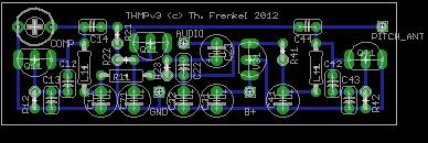
Below you’ll find the schematic and a circuit board layout. Everything is with a 0.1″ spacing, so that the circuit can also be built on a Veroboard, but it should be one with round copper dots. The classic Veroboard with stripes or square copper dots will give too much parasitic capacitance and thus degrade the circuit’s performance.
Have fun building it and don’t hesitate to ask your questions here!


